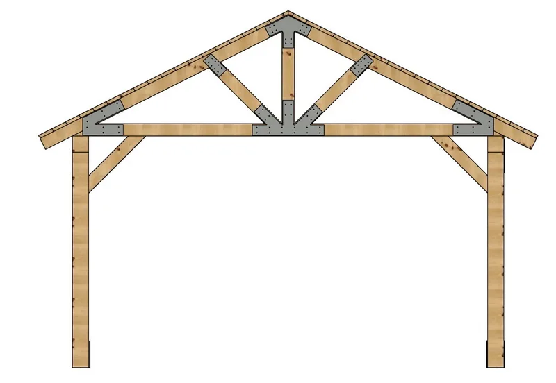
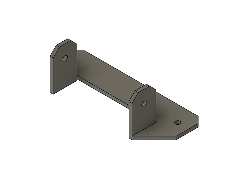
Take a closer look at the plates, bases, and screws that bring your pavilion together. We select the hardware for your design and include the connection details in your kit instructions.
Plates on the front trussConnections throughout the frame
Quality hardware for your pavilion.
Strong connections start with quality hardware. Our structural framing screws are supplied by Big Timber. Your kit includes CTX screws for the timber framing and WTX screws to secure the steel plates.
CTX · Timber framing
Supplied framing sizes: #17 × 8″, 10″, 12″, and 16″.
A structural construction screw with a washer head, star drive, and bronze coating for interior or exterior use. The longer lengths connect substantial timber members; use the length specified for each joint in your kit instructions.
A structural lag screw with a black corrosion-resistant coating, wafer head, and T30 star drive. Its broad head seats against the decorative steel plates, matching their black finish.
Product photos and specifications: Big Timber / Marmon Fastener Company. Images illustrate the product families; they do not depict every screw length supplied.
Counts below are per individual plate, clip, bracket, or base—not the total for a pavilion. Follow your kit’s drawings and hardware schedule for quantities and placement. Decking attachment nails or screws are separate.
Crow’s Foot Plate
King post and webs to bottom chord
Fastener details24 plate screws per piece
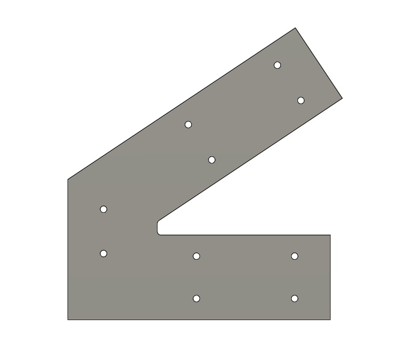
Corner Plate
Bottom chord to top chord
Fastener details10 plate screws per piece
Web Strap
Web to top chord
Fastener details8 plate screws per piece
T Plate
Intermediate header-to-post connection
Fastener details12 plate screws per piece
L Plate
Corner header-to-post connection
Fastener details12 plate screws per piece
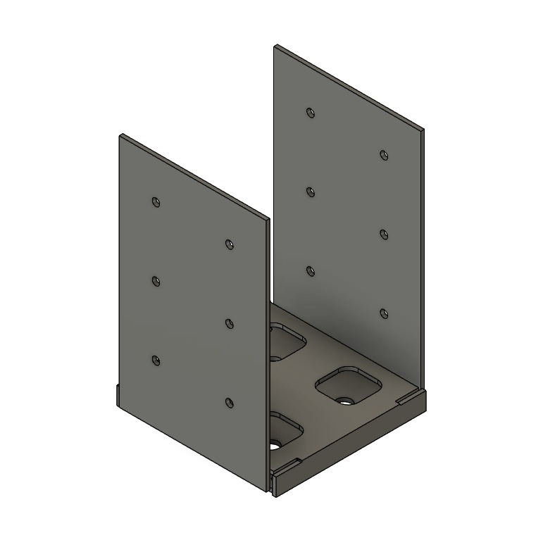
Post Base
Post support connection
Fastener details12 plate screws per piece
The schedule also lists four 5/8″ × 5″ wedge anchors per base. Foundation and anchoring requirements are determined for your project; we do not provide foundation or site engineering.
Solid Peak Plate
Truss peak connection
Fastener details12 plate screws per piece
Slotted Peak Plate
Truss peak connection with ridge-beam opening
Fastener details12 plate screws per piece
Rafter Clip
Rafter-to-header connection
Fastener details4 plate screws per piece
Truss Angle Bracket
Beneath the truss at the header
Fastener details8 plate screws per piece
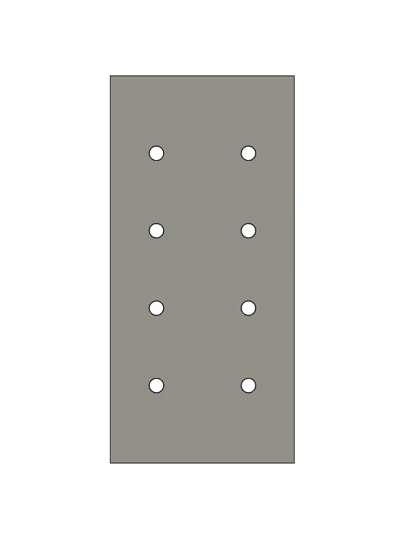
Bottom Splice Plate
Bottom-chord splice for trusses over 20 feet wide
Fastener details12 plate screws per piece
Count follows the illustrated 12-hole pattern.
Component images are illustrative and not to scale. This guide helps you compare kit components; follow your approved project drawings and installation instructions during assembly.